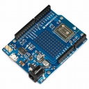
Former product name: ESP-WROOM-02 Development Board
This product was renamed from ESP-WROOM-02 Development Board to ESPr Developer as of June 9th 2016.
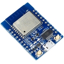
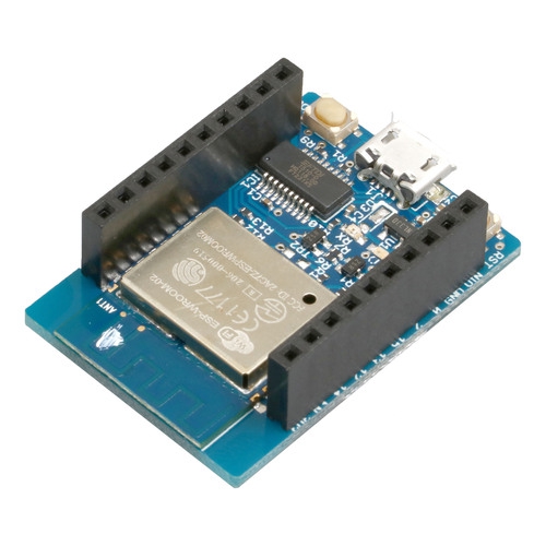
It is a development board with ESP-WROOM-02 and USB Serial converter IC (FT231XS). It also has a 3.3 V output regulator, reset switch and an action mode switcher which enables you to use your ESP-WROOM-02 Wi-Fi right away.
ESP-WROOM-02 Development Board with pre-soldered headers. By using male/male jumper wires, you can easily connect this board to a breadboard without having to solder it.
ESP-WROOM-02 is a 32-bit low power micro-controller (MCU) Wi-Fi Module that integrates TCP/IP network stacks, and includes 10-bit ADC with HSPI, SDIO, UART, PWM, I2C, and I2S interfaces.
The highlight of this board is an FT231X USB-to-Serial converter. That's what translates data between your computer and ESP-WROOM-02.
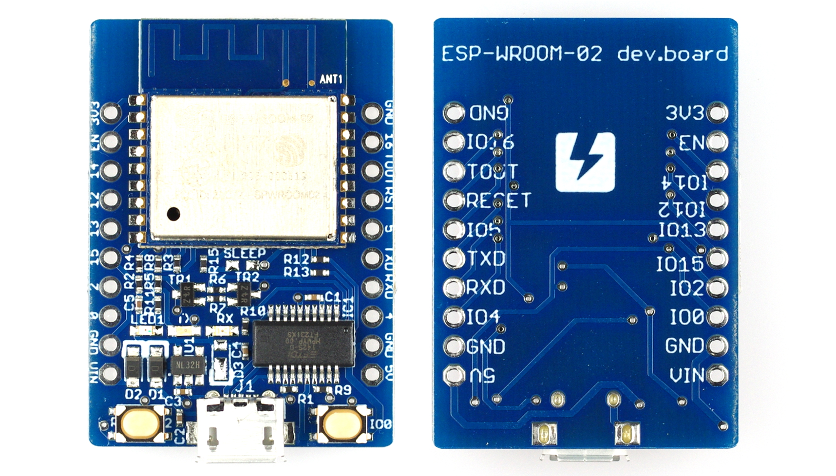
Also defects might occur when using VIN pin with Rev.2 on the back.This has been improved from Rev.3.All the products have switched to Rev.3 as of July 29th 2016.
SPEC
- ESP-WROOM-02
- IEEE 802.11b/g/n (2.4 GHz)
- 32-bit low power micro-controller (MCU)
- 10 bit A/D Converter
- TCP/IP
- SDIO、(H)SPI、UART、I2C、I2S、IrDA、PWM、GPIO
- FCC、CE、Design certified
- Deep sleep mode: Under 10 uA, Off mode: Under 5 uA
- Startup to packet transmission: Under 2 ms
- Power consumption(standby): Under 1 mW(DTIM3)
- Output: +20 dBm(when using 802.11b)
- -40 ℃〜125 ℃
- USB : MicroUSB
- FT231XS on board
- TX,RX signs on LED for correspondence check are reversed.RX will switch when a transmission has been made from ESP-WROOM-02.Alterations are planned from next lot.(July 12th 2016)
- RESET button、MODE Switch Button
- Operation Voltage: 3.3 V
- Power pin
- VIN: 3.7-6 V
- VOUT: Changed name to VOUT pin from 5 V pin.(January 8th 2016)
- Operating voltage: 5 V (fed from USB),Power of VIN will output from VOUT (fed from VIN)
- 3.3 V Pin: For output purpose only
Includes:
- Board X 1
Documents
- Schematic Rev.2(PDF)
- Schematic Rev.3(PDF)
- Product page(English)
- BBS(English)
- Downloads(English)
- ESP8266EX Datasheet Version 4.4(pdf)(English)
- ESP8266 System Description Version 1.4(pdf)(English)
- ESP-WROOM-02 Datasheet Version 0.6(pdf)(English)
- Compliance guide(Japanese)
- Blog entrys(Japanese)
- Developing method for Auduino IDE(Japanese)
- Left Button: RESET, Right button: MODE Switch
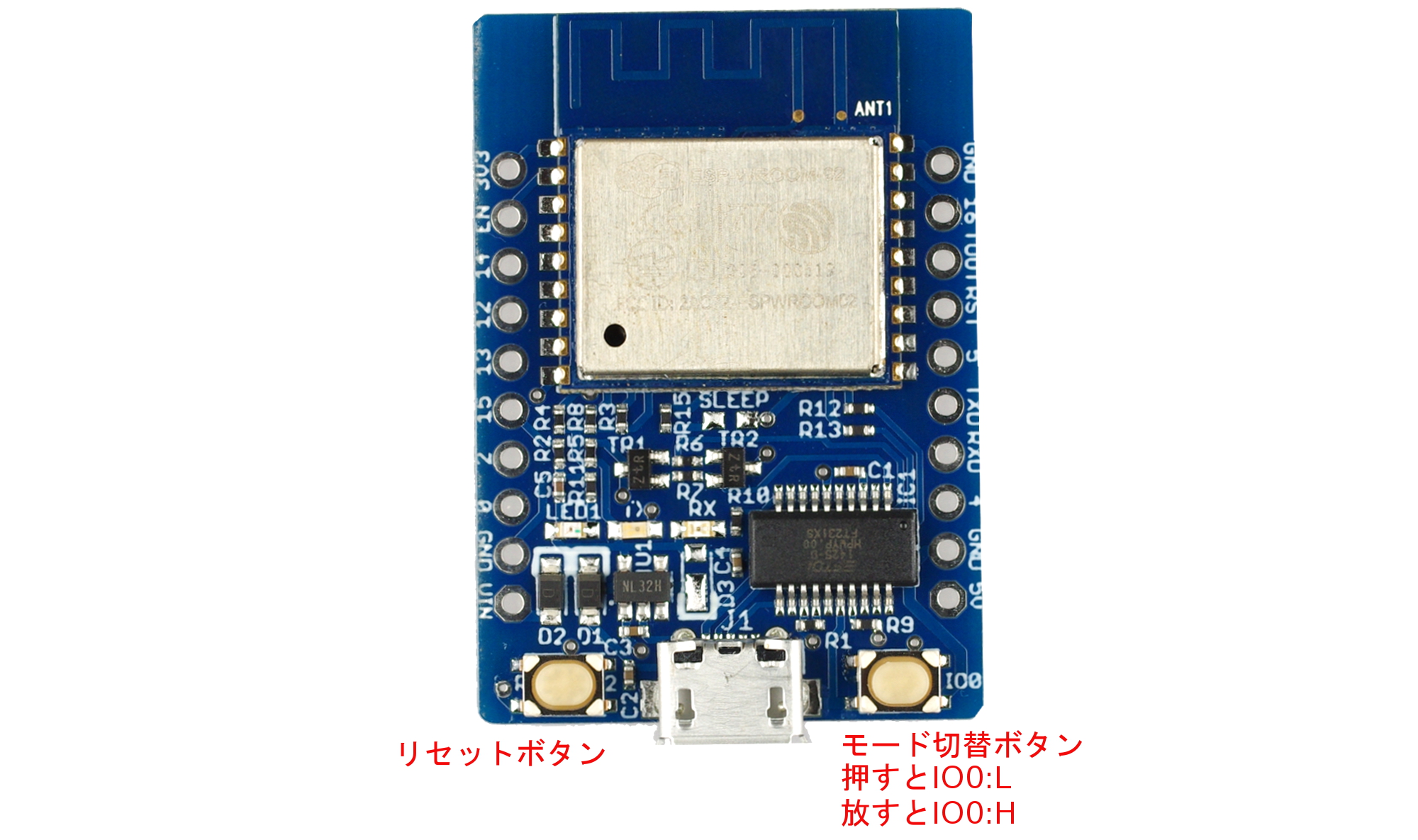
- Push reset button to reset.
- Mode switcher button is attached to IO0 pin. Push IO0 for LOW, free for HIGH.If you reset it from HIGH mode, it will activate at firm ware running mode. If you reset it from LOW mode, it will activate at programming mode.
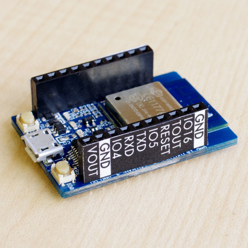
- Please print the pin guide (PDF) and use it as shown below.
Size
Category
|
|
| Name | ESPr® Developer w/ female headers - ESP8266 development board |
|---|---|
| Code | SSCI-026529 |
| SKU# | 2652 |
Related Product
-
ESPr® Developer w/o header - ESP8266 developement board SSCI-025003 (2500)
ESP-WROOM-02 is a 32-bit low power micro-controller (MCU) Wi-Fi Module that integrates TCP/IP network stacks, and includes 10-bit ADC with HSPI, SDIO, UART, PWM, I2C, and I2S interfaces.The highlight of this board is an FT231X USB-to-Serial converter. That’s what translates data between your computer and ESP-WROOM-02.
-
ESPr® Developer environment sensor shield SSCI-027038 (2703)
ESPr Developer Environment sensor shield
-
ESPr® Developer 9-axis IMU shield SSCI-028073 (2807)
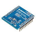
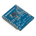
A sensor board equipped with 9 axis sensor LSM9DS1 from ST for ESPr Developer. LSM9DS1 is a 9 axis MEMS sensor equipped with 3 axis Accelerator, 3 Gyrosensor and 3 Magnetometer.
-
ESPr® Developer Grove shield SSCI-028110 (2811)
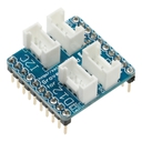
This is a shield to apply GROVE system device for ESPr Developer. It is a Switch Science original board, based on circuit designed by Mr. Shigeru Kobayashi from IAMAS.
-
ESPr® One (Arduino Uno form-factor) SSCI-026208 (2620)
ESP-WROOM-02 WiFi module is loaded on Arduino compatible board. There are redundant pins on this board, because GPIO pins of ESP-WROOM-02 are lesser than Arduino. Only one A0 analog input pin. Although it is compatible to Arduino please be aware that it might not operate properly depending on choice of shield. Please refer to How to develop with Arduino IDE for more details. Operating voltage of input/output pin is 3.3 V.
-
ESP-WROOM-02 Breakout Pro SSCI-023474 (2347)
ESP-WROOM-02 Breakout Pro
-
ESP-WROOM-02 Breakout Simple SSCI-023412 (2341)
ESP-WROOM-02 Breakout Simple
-
ESP-WROOM-02 Breakout type T SSCI-025805 (2580)
ESP-WROOM-02 Breakout type T

