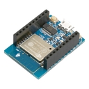
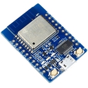
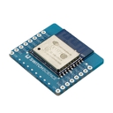
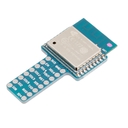
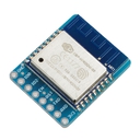
Former product name: ESP-WROOM-02 Development Board - Uno Pinout
This product was renamed from ESP-WROOM-02 Development Board - Uno Pinout to ESPr One as of June 9th 2016.
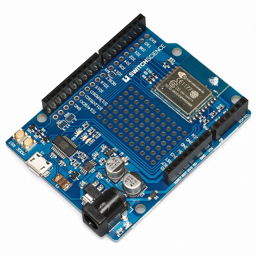
ESP-WROOM-02 WiFi module is loaded on Arduino compatible board. There are redundant pins on this board, because GPIO pins of ESP-WROOM-02 are lesser than Arduino. Only one A0 analog input pin. Although it is compatible to Arduino please be aware that it might not operate properly depending on choice of shield. Please refer to How to develop with Arduino IDE for more details. Operating voltage of input/output pin is 3.3 V.
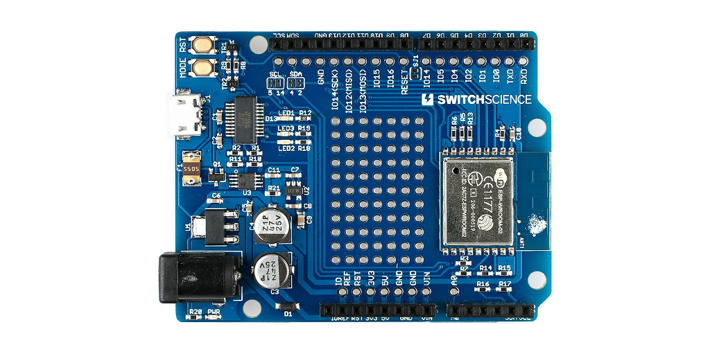
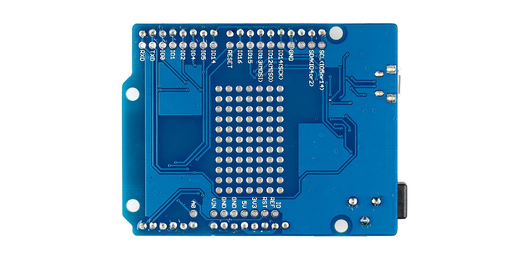
SPEC
- Power
- DC jack: DC7 ~ 12 V
- USB:DC5 V
- Operating Voltage: 3.3 V
- ESP-WROOM-02
- IEEE802.11b/g/n(2.4 GHz)
- 32-bit low power micro-controller (MCU)
- 10 bit A/D Converter
- TCP/IP
- SDIO、(H)SPI、UART、I2C、I2S、IrDA、PWM、GPIO
- FCC、CE、Design certified
- Deep sleep mode: Under 10 uA, Off mode: Under 5 uA
- Startup to packet transmission: Under 2 ms
- Power consumption(standby): Under 1 mW(DTIM3)
- Output: +20 dBm(when using 802.11b)
- -40 ℃〜125 ℃
- USB : MicroUSB
- FT231XS on board
- RESET button、MODE Switch Button
- LED1: Usage is same as Arduino D13. #14 Digital pin is assigned.
- Universal Area
- 7 X 11 (2.54 mm pitch)
- Short jumper
- SJ1: Use D8 pin for reset.
- SCL: Rearrange SCL pin to GPIO5 or 14(default5)
- SDA: Rearrange SDA pin to GPIO4 or 2 (default4)
- Buttons: Switch to manual for program reading.No need to use buttons when reading from Arduino IDE.For details.
- Reset button(RST)
- Mode Switcher(MODE): GP1IO will turn to LOW while pushing
- Analog input: A0 only. Input range: 0 ~ 3.3 V (Switches to 0 ~ 1.0 V on board)
- Some of D3 pins with IO1 are unconnected to be exact.
- IO0,IO2,IO15 are used as setup pins for ESP-WROOM-02 so they are set on pull up, pull down mode. We recommend other pins for general in/output.
Includes:
- Board X 1
Documents
- How to develop with Arduino IDE
- About Digital I/O
- ESP8266 Arduino Core(Github)
- Ver2.1.0 does not correspond to MODE2, MODE3 on SPI.(March 15th 2016)
- Print Pin Guide and apply it shown below.
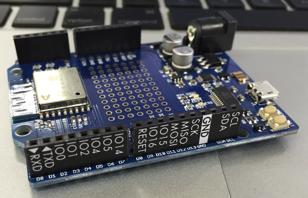
Comparision of pin layout
| Arduino Uno R3 | ESPr One |
|---|---|
| D0(RXD) | RXD |
| D1(TXD) | TXD |
| D2 | IO0 |
| D3 | Disconnected |
| D4 | IO2 |
| D5 | IO4 |
| D6 | IO5 |
| D7 | IO14 |
| D8 | Reset(Can detach by SJ1) |
| D9 | IO16 |
| D10 | IO15 |
| D11 | IO13(MOSI) |
| D12 | IO12(MOSI) |
| D13 | IO14(SCK) |
| GND | GND |
| AREF | No connection |
| SDS | IO4 or IO2 (use short jumper to switch: Default IO4) |
| SCL | IO5 or IO14 (use short jumper to switch: Default IO5) |
| A0 | A0 (Convert A0:0 ~ 3 V to TOUT:0 ~ 1 V by Resistive dividing converter) |
| A1 | No connection |
| A2 | No conncetion |
| A3 | No connection |
| A4(SDA) | IO4 or IO2 (use short jumper to switch: Default IO4) |
| A5(SCL) | IO5 or IO14(use short jumper to switch: Default IO5) |
Category
|
|
| Name | ESPr® One (Arduino Uno form-factor) |
|---|---|
| Code | SSCI-026208 |
| SKU# | 2620 |
Related Product
-
ESPr® Developer w/ female headers - ESP8266 development board SSCI-026529 (2652)
ESPr® Developer w/ female headers - ESP8266 development board
-
ESPr® Developer w/o header - ESP8266 developement board SSCI-025003 (2500)
ESP-WROOM-02 is a 32-bit low power micro-controller (MCU) Wi-Fi Module that integrates TCP/IP network stacks, and includes 10-bit ADC with HSPI, SDIO, UART, PWM, I2C, and I2S interfaces.The highlight of this board is an FT231X USB-to-Serial converter. That’s what translates data between your computer and ESP-WROOM-02.
-
ESP-WROOM-02 Breakout Pro SSCI-023474 (2347)
ESP-WROOM-02 Breakout Pro
-
ESP-WROOM-02 Breakout type T SSCI-025805 (2580)
ESP-WROOM-02 Breakout type T
-
ESP-WROOM-02 Breakout Simple SSCI-023412 (2341)
ESP-WROOM-02 Breakout Simple

