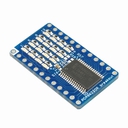
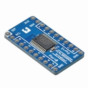
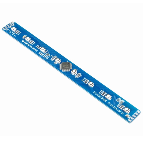
This RGB LED Stick-8ch is an I²C-bus controlled 24-bit LED driver board that uses the PCA9626B by NXP. Each channel can be controlled by PWM, which enables the stick to display intermediate colors.
The stick has 8 full color LEDs on every 3 channel.Therefore, all you have to do is connect it to I2C bus and issue a command to get a full color LED to set it to a specific brightness value.
Also, this LED is allocated linearly giving it an even spacing when applied to other boards.
Please refer to Product page or Data sheet for ways to control.
Spec (General function of IC)
- Supply voltage range: 3.3 V ~ 5.5 V
- Individual constant current LED port for 24 channels
- Output enable function on all LED port
- All ports have on/off and 8 bit resolution (256 steps) controlled by PWM
- All ports have individual / group controller
- 8 full color LED
- Output peak current: 100 mA
- Signal pin for external drive
- Interface: I2C
- Programmable I2C address (0 × 80 at default)
- Pattern on Pull-up resistor for I2C (resistor not included)
Cautions
-
About pin header
Please prepare the pin header by yourself and solder it depending on your purpose. -
About Output enable function on LED port
PCA9626B has an Output enable pin (OE), however is connected to GND at default.
When using OE pin, cut the internal pattern on SJ8 to detach it from GND. -
About pull-up resistor for I2C
The pull-up resistor for I2C is not mounted at default.If you want to add it, solder chip resistor on R25 and R26 (chip size:1608). -
About I2C slave address
The default address is 0 × 80 (1000 000X) due to solder jumper (SJ7 ~ SJ1). You can change the lower address easily by processing solder jumper (SJ3, SJ2, SJ1) on board. If you want to change upper address, you will need to process solder jumper (SJ7, SJ6, SJ5, SJ4). First, cut the pattern on jumper and then, connect it to VDD (1) or GND (0) with a cable adjusting it to 1/0.

Surface
Back
Application example(1) "When connected to Raspberry Pi"
The allocation of pins on the left side(the side with most pins) of this board can be inserted directly to 1,3,5,7,9 pins on extension connector of Raspberry Pi. Therefore, assembling L connector with 5 pins is possible.Please see below.
Application example(2) "When using more than one module"
When you want to expand board to 16 LEDs by using two modules,
1) Prepare two modules
2) Process solder jumper on either module and change address to 0 × 82.
3) Don't change anything on the other one and connect them in a line

4) Access both to 0 × 80 and 0 × 82 and coordinate the movements.
By doing this, the board will look like one module with 16 LEDs linearly aligned with an even spacing.
Documents
Category
|
|
| Name | PCA9626B RGB LED Stick - 8ch with PCA9626B |
|---|---|
| Code | SSCI-025409 |
| SKU# | 2540 |
Related Product
-
Breadboard EIC-801 (313)
Basic breadboard
-
Jumper Wires M/M Pack of 10 EIC-UL1007-MM-015 (620)
Jumper Wires M/M Pack of 10
-
PCA9632DP1 I2C 4ch LED driver board with 4 LEDs onboard SSCI-023788 (2378)
PCA9632DP1 I2C 4ch LED driver board with 4 LEDs onboard
-
PCA9624PW I2C 8ch LED driver board with 8 LEDs onboard SSCI-023894 (2389)
PCA9624PW I2C 8ch LED driver board with 8 LEDs onboard
-
PCA9622DR I2C 16ch LED driver borad with 4x4 LEDs onboard SSCI-023887 (2388)
PCA9622DR I2C 16ch LED driver borad with 4x4 LEDs onboard
-
PCAL9555APW I2C GPIO Expander SSCI-023528 (2352)
PCAL9555APW I2C GPIO Expander

