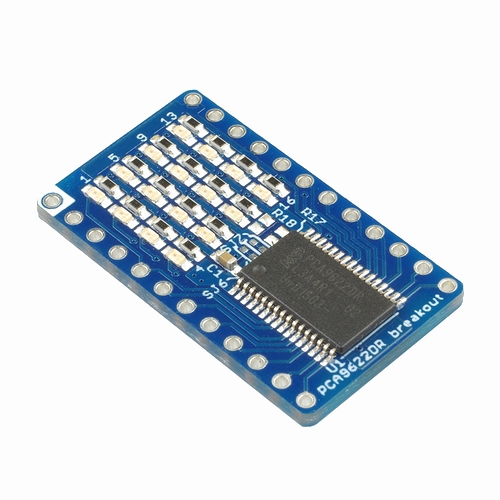
This I²C-bus controlled 16-bit LED driver chip is for PCA9622DR by NXP. The PWM controller adjusts the brightness of LEDs.
The on-board 16 LEDs will blink smoothly just by connecting it to I²C-bus and issuing a command. LEDs are arranged in an evenly spaced 4x4 grid.
For more controlling method, please refer to product page or PCA9622DR Datasheet.
Features
-
Supply voltage range: 2.3 V ~ 5.5 V
-
Individual LED port for 16 channels
-
Output enable function on all LED port
-
All ports have on/off and 8 bit resolution (256 steps) controlled by PWM
-
All ports have individual / group controller
-
16 Red LEDs
-
Output peak current : 100mA
-
Signal pin for external drive
-
Interface: I²C
-
Pull-up resistor for I²C (not included)
Precautions
-
Pin header
Please purchase the pin header separately and solder them depending on each use. -
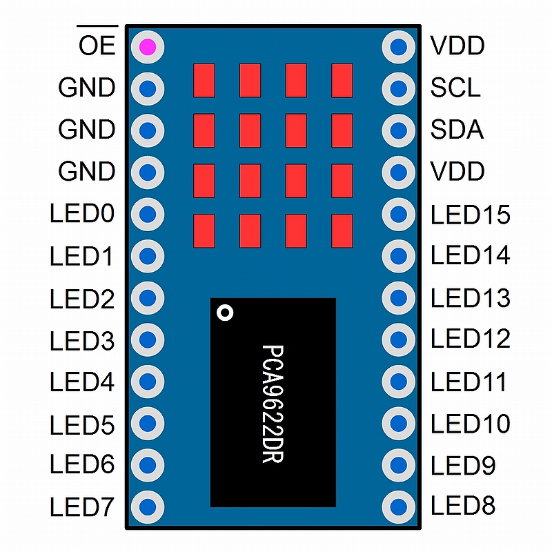
Output enable function on LED port
Although PCA9622DR has an output enable pin (OE), LED port is fixed to output mode because it is connected to GND at default.
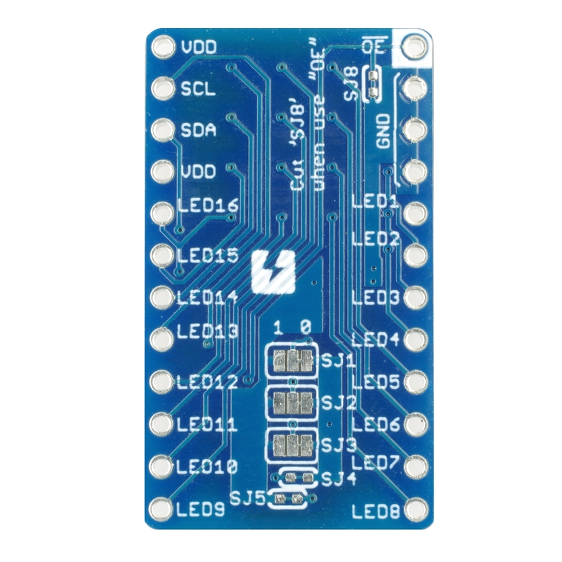
If you cut jumper (SJ8) on back, OE pin will come into effect and you will be able to control it by external devices. -
I2C pull-up resistor
Pull-up resistor is not included. If you want to add it, please solder chip resistor (size 1608) on R17, R18 on board. -
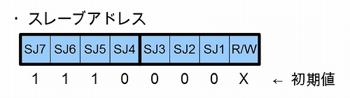
I2C address
Default address is setup to 0×E0 (1110 000X) by solder jumper (SJ7 ~SJ1). You can change bottom side of I2C address easily by processing solder jumper (SJ3, SJ2, SJ1) on back of board.If you want to change address of upper side, you will need to process solder jumper (SJ7, SJ6) on surface and solder jumper (SJ5, SJ4) on back of board. To do this, first you will have to cut the pattern and then connect wire to VDD (1) or GND (0).
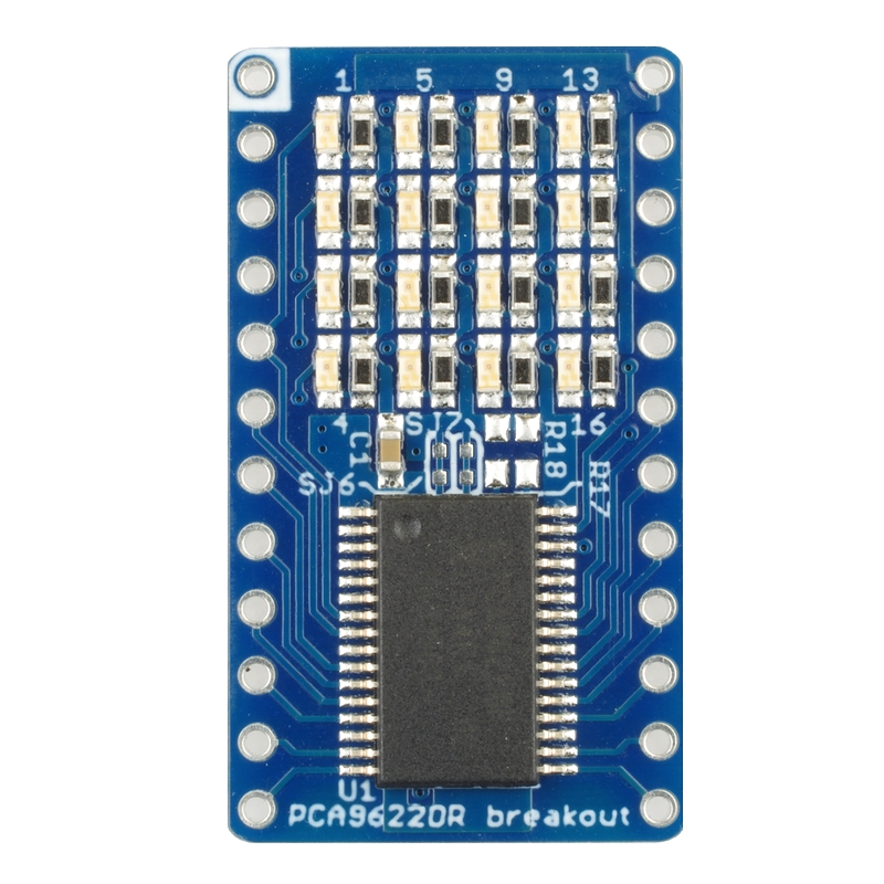
Layout
Surface
Back
Documents

Category
|
|
| Name | PCA9622DR I2C 16ch LED driver borad with 4x4 LEDs onboard |
|---|---|
| Code | SSCI-023887 |
| SKU# | 2388 |
Related Product
-
 Breadboard EIC-801 (313)
Basic breadboard
-
 Jumper Wires M/M Pack of 10 EIC-UL1007-MM-015 (620)
Jumper Wires M/M Pack of 10
-
 PCA9632DP1 I2C 4ch LED driver board with 4 LEDs onboard SSCI-023788 (2378)
PCA9632DP1 I2C 4ch LED driver board with 4 LEDs onboard
-
 PCA9624PW I2C 8ch LED driver board with 8 LEDs onboard SSCI-023894 (2389)
PCA9624PW I2C 8ch LED driver board with 8 LEDs onboard
-
 PCAL9555APW I2C GPIO Expander SSCI-023528 (2352)
PCAL9555APW I2C GPIO Expander
-
 SC16IS750 UART with I2C bus interface breakout board SSCI-023108 (2310)
The breakout board for the chip SC16IS750 converts I2C or SPI serial signals to UART. It is handy for expanding a serial port when using microcontrollers.