PCA9632DP1 I2C 4ch LED Board that uses PCA9632DP1 by NXP, an I²C-bus controlled 4-bit LED driver. An individual PWM controller makes the brightness value of LED adjustable.
This board itself already has LEDs on, so 4 LEDs will blink just by connecting it to the I2C bus. When laying multiple of this board, LEDs are evenly spaced in linear alignemnet.
To find detailed information on how to controll, please go to the manufacturer's site and the PCA9632DP1 data sheet
Specification (major functions of the IC)
- Operating voltage: 2.3V ~ 5.5V
- 4ch individual LED port
- 8-bit resolution (256 steps) fixed frequency Individual PWM controller
- Individual /Group PWM controller
- 4 red LEDs on the board
- Sinks 24 mA into the LED port
- Signal pin for external drive on board
- interface: I2C
- Has patterns for I2C pull up resistor (Resistor not included)
Caution
- The I2C address is fixed to 0xC4(1100 010x)and can not be changed.
- Please prepare pin headers separately and solder them accordingly.
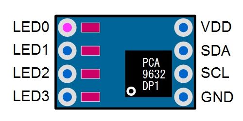
◆ Pin allocation
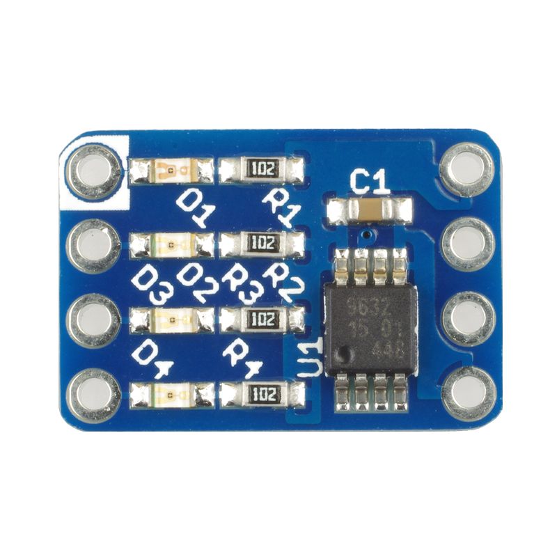
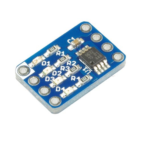
◆ Surface
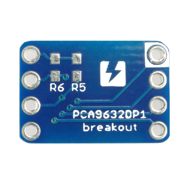
◆ Back
◆ Documents
◆Sample code (Arduino)
- Sample1
The 4 LEDs will light up all at once
#include <Wire.h> //I2C通信用

#define PCA9632_DEV_ID 0x62 //全体制御用のI2Cアドレス
void setup()
{
  pinMode(13, OUTPUT); //debug用
  Wire.begin(); //Arduinoがマスター
  /*起動時の処理*/
  Wire.beginTransmission(PCA9632_DEV_ID);//送信先のアドレスを指定して通信開始
  Wire.write(0x00); //MODE制御用のレジスタ
  Wire.write(B10000001); //デフォルトがSLEEP:ENABLEでB100[1]0001になってるので注意
  Wire.endTransmission(); //通信終了
  delay(500);
}

void loop()
{
  /*点灯*/
  digitalWrite(13, HIGH);        //debug用
  Wire.beginTransmission(PCA9632_DEV_ID);
  Wire.write(0x08);             //LED制御用のレジスタアドレス
  Wire.write(B01010101);        //2bit×4個分の点灯制御//00=消灯//01=強制点灯//10=個別PWM制御もON//11=全体PWM制御もON
  Wire.endTransmission();
  delay(500);

  /*消灯*/
  digitalWrite(13, LOW);
  Wire.beginTransmission(PCA9632_DEV_ID);
  Wire.write(0x08);
  Wire.write(0B00000000);
  Wire.endTransmission();
  delay(500);
}
- Sample2
2 LEDs will light up out of 4. Brightness can be controlled individually.
#include <Wire.h> //I2C通信用

#define PCA9632_DEV_ID 0x62 //全体制御用のI2Cアドレス

void setup()
{
  pinMode(13, OUTPUT); //debug用
  Wire.begin(); //Arduinoがマスター
  /*起動時の処理*/
  sendI2C_single(0x00, B10000001); //MODE1//デフォルトがSLEEP:ENABLEでB100[1]0001になってるので注意
  sendI2C_single(0x01, B00100001); //MODE2//全体PWM制御を点滅モードに設定 DMBLNK=1
  sendI2C_single(0x02, B00001111); //PWM0//暗め(データシートp12式1)
  sendI2C_single(0x03, B11111111); //PWM1//明るめ(p12式1)
  sendI2C_single(0x04, B00001111); //PWM2//暗め(p12式3)
  sendI2C_single(0x05, B11111111); //PWM3//明るめ(p12式3)
  sendI2C_single(0x06, B01111111); //GRPPWM//全体PWMのduty比を1:1に(p13式5)
  sendI2C_single(0x07, B00010111); //GRPFREQ//全体PWMの周期を約1secに(p14式7)
  sendI2C_single(0x08, B11111010); //LEDOUT//3,2,1,0//00=消灯//01=強制点灯//10=個別PWM制御もON//11=全体PWM制御もON
  delay(1);
}

void loop()
{
  /**************  LED3,2は10で個別PWMにより調光されている  LED1,0は11で個別PWMによって調光された上で、点滅モードの全体PWMで点滅している  **************/
}

/*データ送信用簡易関数*/
void sendI2C_single(byte REG, byte DATA)
{
  Wire.beginTransmission(PCA9632_DEV_ID);//送信先のアドレスを指定して書き込み用に通信開始
  Wire.write(REG);//データを書き込むレジスタアドレスを送信
  Wire.write(DATA);//データを送信
  Wire.endTransmission(); //通信終了
}
Category
|
|
| Name | PCA9632DP1 I2C 4ch LED driver board with 4 LEDs onboard |
|---|---|
| Code | SSCI-023788 |
| SKU# | 2378 |
Related Product
-
 Breadboard EIC-801 (313)
Basic breadboard
-
 Jumper Wires M/M Pack of 10 EIC-UL1007-MM-015 (620)
Jumper Wires M/M Pack of 10
-
 PCA9622DR I2C 16ch LED driver borad with 4x4 LEDs onboard SSCI-023887 (2388)
PCA9622DR I2C 16ch LED driver borad with 4x4 LEDs onboard
-
 PCA9624PW I2C 8ch LED driver board with 8 LEDs onboard SSCI-023894 (2389)
PCA9624PW I2C 8ch LED driver board with 8 LEDs onboard
-
 PCAL9555APW I2C GPIO Expander SSCI-023528 (2352)
PCAL9555APW I2C GPIO Expander
-
 SC16IS750 UART with I2C bus interface breakout board SSCI-023108 (2310)
The breakout board for the chip SC16IS750 converts I2C or SPI serial signals to UART. It is handy for expanding a serial port when using microcontrollers.