This board has PCA9629APW, the stepping motor controller IC by NXP, soldered onto a breakout board.Output wave train is programmable using control registers. The control registers are programmed via the I²C-bus.
This board is an IC controller and does not have a motor driver. Please choose an appropriate driver on your own.
Spec
- Operating voltage: 4.5 V ~ 5.5 V.
- Controls four Unipolar stepping motor coils
- Four balanced push-pull type outputs capable of sinking 25 mA or sourcing 25 mA
- One-phase (wave drive), two-phase, and half-step drive format logic level outputs
- Programmable motor action either multiple times (1 to 255) or continuously
- Programmable re-start motor with new speed and operation while motor is still running
- Programmable ramp-up on start and ramp-down to stop
- 32-bit step counter to count output steps
- Programmable watchdog timer with option to generate interrupt, reset device or stop motor
- Four general purpose I/Os: P0 to P3
- A variety of interrupting features from IC
- Interface: I2C
- I2 address: 0 × 40 (0100 000x) ~ 0 × 5E (0101 111x)
- A pattern signal on pull-up resistor for I2. (resistor is not included)
Cautions
-
About pinheader
Please prepare the pin header by yourself and solder it depending on your purpose. -
About pull-up resistor for I2C.
The pull-up resistor for I2C is not included at default. If you are thinking of adding, please solder chip resistor to R1 and R2 on back of board (chip size: 1608). When doing this, please be advised to assemble chip resistor first, because the distance between chip resistor and pin header is close. -
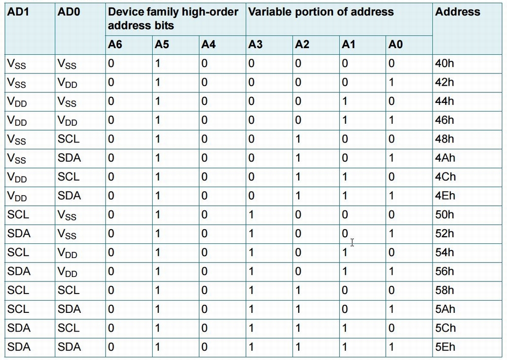
About I2C address
Default address is 0 × 44 (0100 010X) according to solder jumper (AD1, AD0) on back of board.
You can change I2C address by processing solder jumper as shown on below chart.
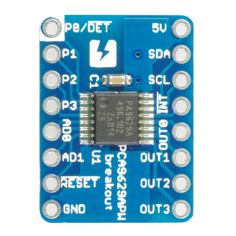
Surface
Back

Documents
Category
|
|
| Name | PCA9629APW stepping motor driver breakout board |
|---|---|
| Code | SSCI-023740 |
| SKU# | 2374 |
Related Product
-
 Breadboard EIC-801 (313)
Basic breadboard
-
 Jumper Wires M/M Pack of 10 EIC-UL1007-MM-015 (620)
Jumper Wires M/M Pack of 10
-
 PCAL9555APW I2C GPIO Expander SSCI-023528 (2352)
PCAL9555APW I2C GPIO Expander
-
 PCF2129AT real time clock with SPI/I2C bus interface breakout board SSCI-023535 (2353)
PCF2129AT real time clock with SPI/I2C bus interface breakout board
-
 SC16IS750 UART with I2C bus interface breakout board SSCI-023108 (2310)
The breakout board for the chip SC16IS750 converts I2C or SPI serial signals to UART. It is handy for expanding a serial port when using microcontrollers.
-
 MCP23017 GPIO Expander for Raspberry Pi SSCI-016506 (1650)
16-port I/O expander for Raspberry Pi. MCP23017 by Microchip is mounted on the expander.