An ESPr Developer semi finished kit with Ultra low power consumption color LCD (Japanese page) from JDI (Japan Display Inc).
The components needed to operate the LCD are fully mounted, making it easier to get started for those who are not eager to solder.
The pin headers on the shield can be inserted to the breadboard too, allowing it to also work as a pitch converter board for the LCD.
Please be advised that this product is a semi finished item, therefore the LCD must be fixed manually onto the board. The spacer for fixation is included in the kit, however please prepare double sided tape (commercially available) separately.
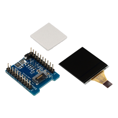
Includes
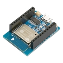
- Fully mounted ESPr Developer board
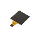
- Ultra low power consumption color LCD (JDI)
- Spacer for fixation
Specification
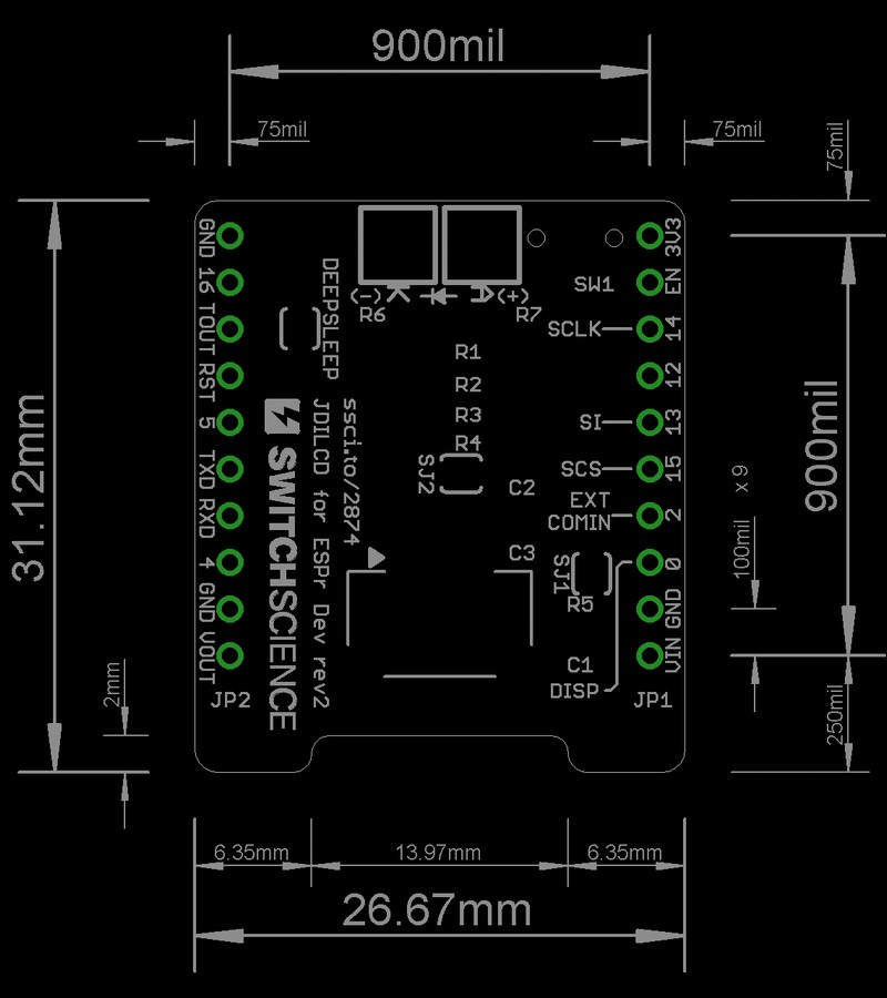
- ESPr Developer board
- Pin headers fully assembled
- Connector for LCD on board
- Versatile push button - 1 port (connect to GPIO)
- LED pad for illumination on board (connect to GPIO)
Pins
| GPIO | Direction※ | Connector pin# | Where to connect | Signal details |
|---|---|---|---|---|
| IO15 | O | JP1 - 5 | SCS (LCD connector) | Chip selector |
| IO14 | O | JP1 - 8 | SCLK (LCD connector) | Clock |
| IO13 | O | JP1 - 6 | SI (LCD connector) | Data |
| IO0 | O | JP1 - 3 | DISP (LCD connector) | ON/OFF signal, "H" for indication |
| IO2 | O | JP1 - 4 | open | Connects to EXTCOMIN (connector) by shortening SJ2 |
| IO5 | O | JP2 - 6 | LED Pad(K) | Output for LED (option) |
| IO4 | I | JP2 - 3 | Switch(SW1) | Versatile push button |
※The direction is observed from EsPr Developer
Display setting
[SJ1] decides action mode of LCD. The connector "EXTMODE" signal and GND are connected through [SJ1] at default. Also, the LCD should work just by running the software, enabling you to use it without any manipulation.
How to assemble
-
Lift up the black part on the connector, and insert the FPC of LCD. The junction (golden pattern) of FPC pin should face downwards.
-
Lower down the black part on connector and fix the FPC.
-
Over turn the board and stick the spacer with double sided tape.
-
Stick double sided tape on top of spacer too.
-
Fold the LCD down onto the spacer and you are finished assembling!
Please remove the IR protective liner on the surface when assembling.
About the LED for illumination
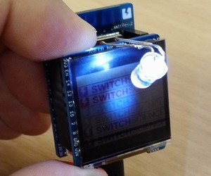
LEDs are optionally addable on to the shield. They can be connected directly to the connecting pad with current limit resistor. Please prepare white LEDs separately and solder them depending on your usage.
The LED pad is connected to versatile port, therefore by internalizing the software with the push button on the board, you will be able to control ON/ OFF of the LEDs.
Surface
Back
Document
Category
|
|
| Name | Reflective color LCD shield for ESPr® Developer |
|---|---|
| Code | SSCI-028745 |
| SKU# | 2874 |
Related Product
-
MIP Reflective color LCD module 1.28" w/o backlight JDI-LPM013M126A (2858)
Ultra-low power consumption color reflective LCD module from JDI (Japan Display Inc.). Introduction of proprietary reflective color technology made it possible for you to enjoy clear visibility even under the direct sunlight. Communication method and size are SPI and 1.28 model respectively.
-
ESPr® Developer w/ female headers - ESP8266 development board SSCI-026529 (2652)
ESPr® Developer w/ female headers - ESP8266 development board
-
Breadboard EIC-801 (313)
Basic breadboard
-
Jumper Wires M/M Pack of 10 EIC-UL1007-MM-015 (620)
Jumper Wires M/M Pack of 10
-
128x48 Graphic Display - AQM1248A SSCI-026086 (2608)
128x48 Graphic Display - AQM1248A

