test
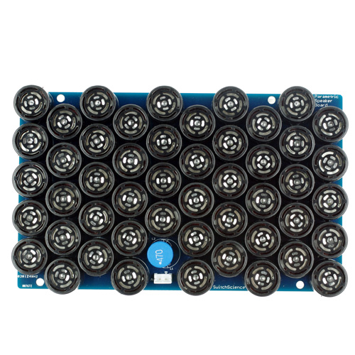
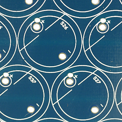
This product is a speaker kit which delivers sound only straight ahead with a sharp directivity enabled by ultrasound. As you can see in the picture below, it has many wave transmitters. So you will need to solder all of them to the speaker PCB.
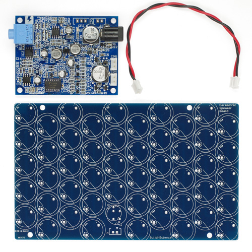
Includes:
- 1 x Amplifier PCB (assembled)
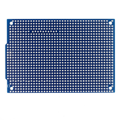
- 1 x Speaker PCB (not assembled)
- 49 x Wave transmitters
- 1 x Inductor for the speaker PCB
- 1 x Connector for the speaker PCB
- 1 x Connection cable for the amplifier PCB to the speaker PCB
- 1 x Slide power switch for the amplifier PCB
Besides the items shown in the picture below, the kit includes wave transmitters, an inductor, a connector and a slide power switch.
Specifications:
- Power input: DC 12 V, 1A, Outer diameter 5.5 mm, Inner diameter 2.1 mm Center-positive, Barrel-negative
- Audio input: 3.5 mm Stereo mini jack
- Max number of ultrasound transmitters: 100 (for over 50 transmitters, you need 2 A AC adaptor)
After soldering:
Cautions:
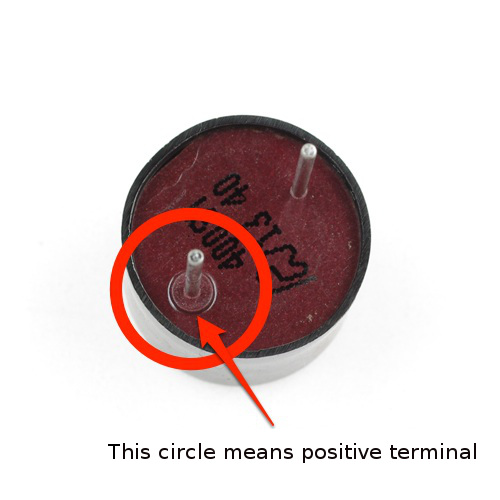
Wave transmitters have a polarity. The positive terminal of the transmitters matches the positive signed hole of the PCB.
The inductor does not have a polarity. Please refer to the picture below to see how you can solder the inductor. The PCB has several holes so that it is suitable for several types of the inductors.
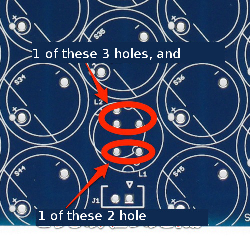
You can insert each of two legs of an inductor to one of the 2 holes and to the 3 holes as shown above.
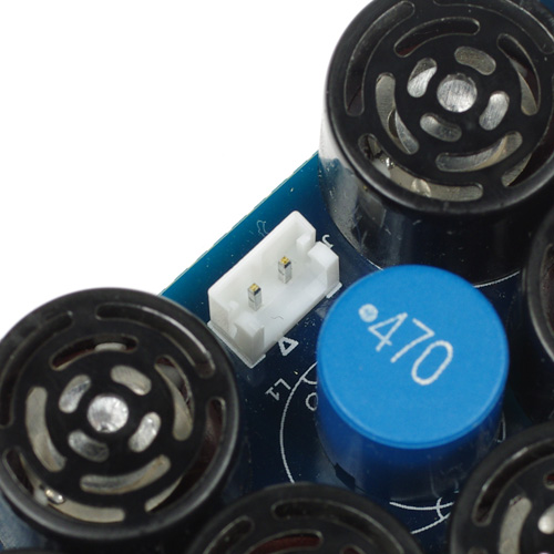
And you need to solder the connector to the PCB. Please see the picture below.
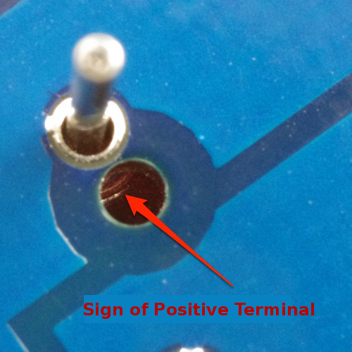
There is a hole on the positive side of the PCB for checking the polarity of a transmitter.
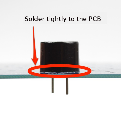
You need to solder the transmitters to the PCB tightly. If there is a gap in between, the performance of the speaker it is not possible to exhibit the best performance, because it cannot align the direction of the transmitters.
Schematic:
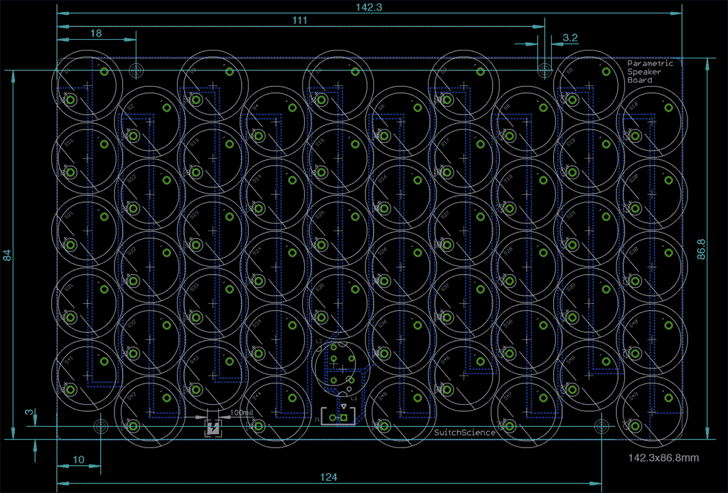
All hole sizes are Φ3.2mm.PDF
Category
|
|
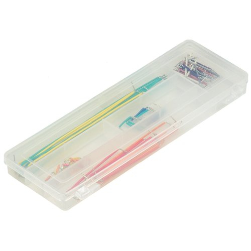
| Name | Jumper Wires for Breadboard |
|---|---|
| Code | EIC-J-S |
| SKU# | 314 |
Related Product
-
 Breadboard EIC-801 (313)
Basic breadboard
-
 Jumper Wires M/M Pack of 10 EIC-UL1007-MM-015 (620)
Jumper Wires M/M Pack of 10